Logic Analyzer Extensions


Record Digital and Analog Signals and Correlate Them to Program Flow
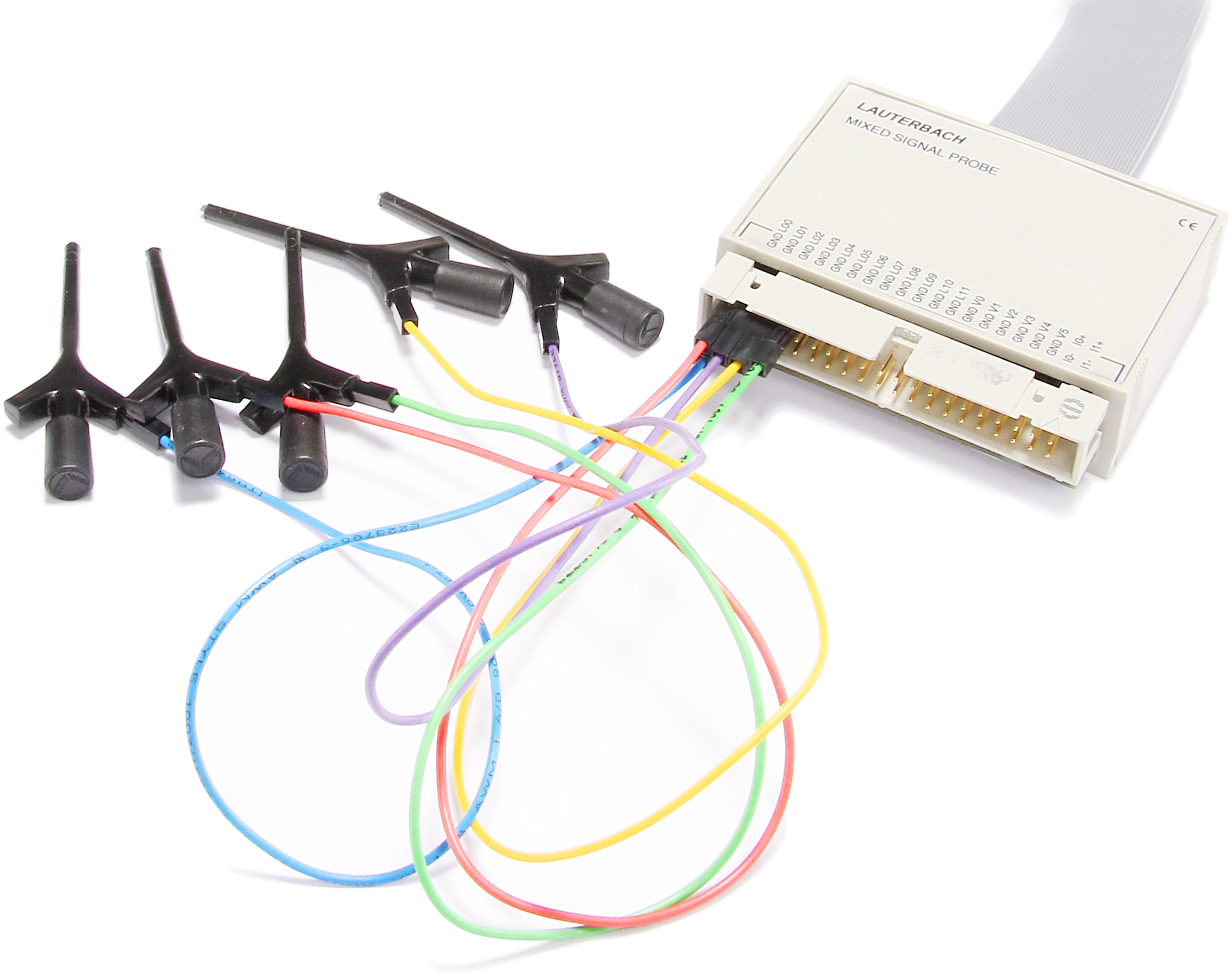
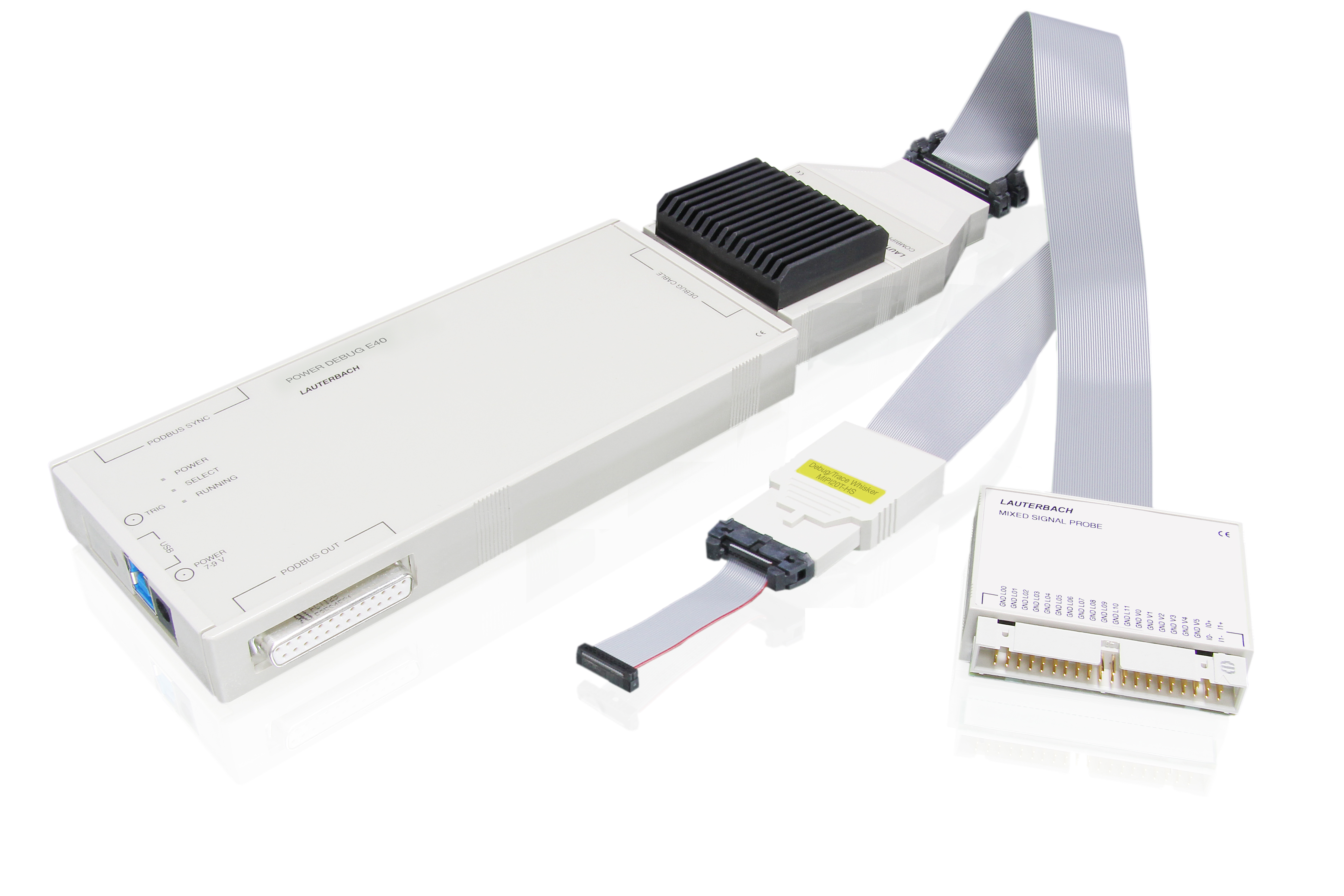
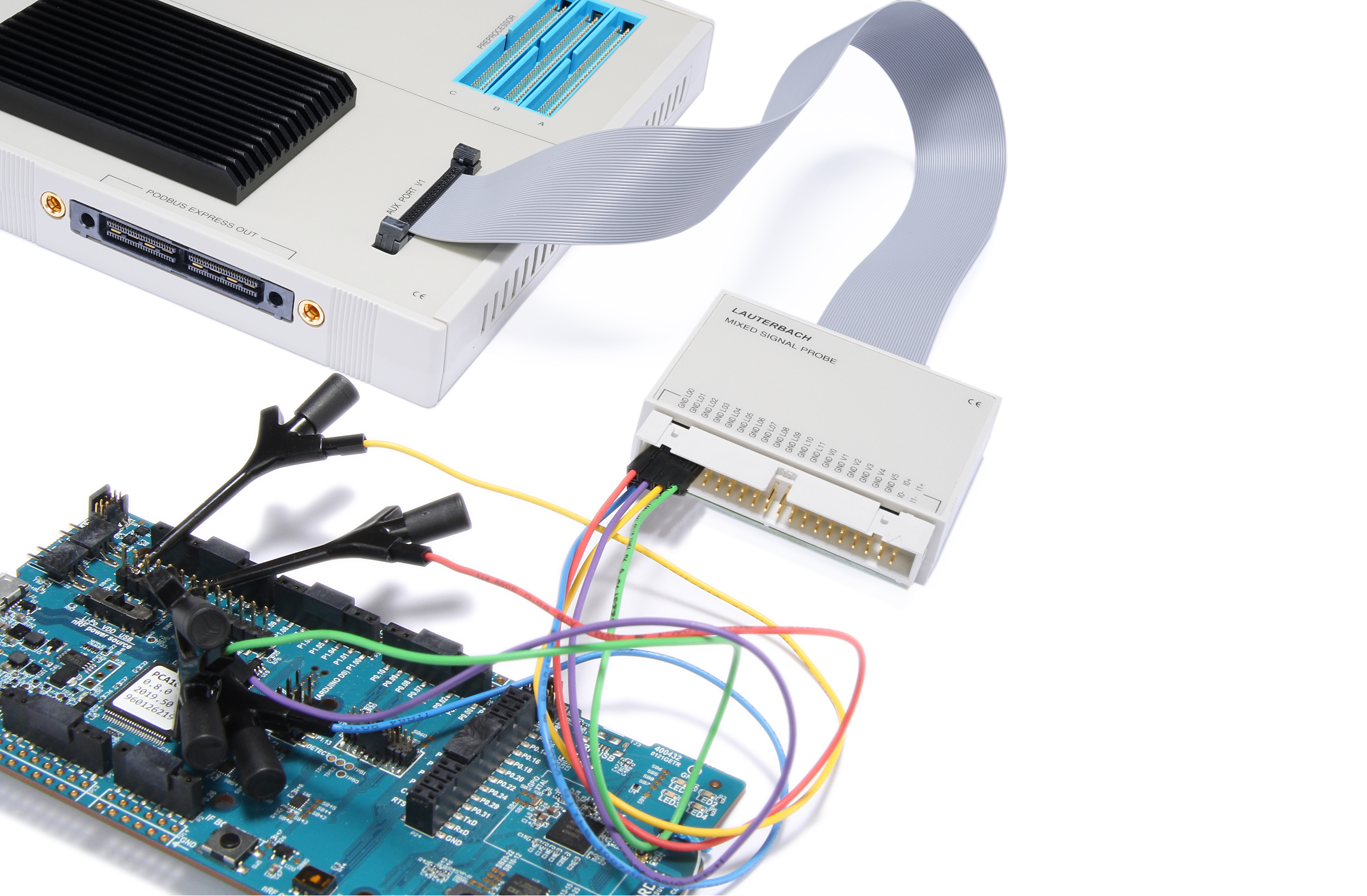
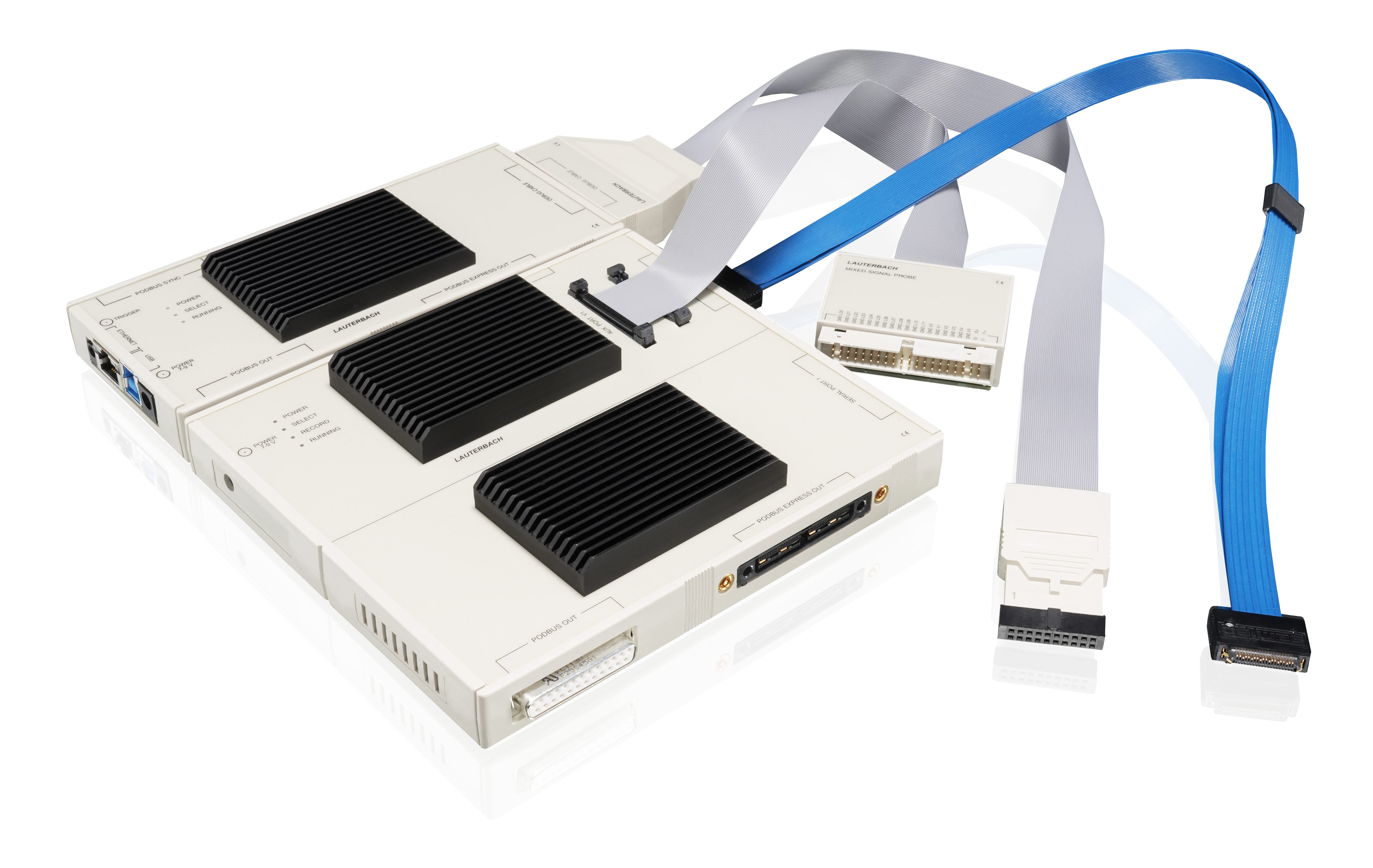
Our logic analyzers are the perfect extensions to our debug and trace tools. They allow the recording of digital and analog signals, which can be correlated to the recorded program flow. This way it is easy to verify signal-timings which are initiated by the application software or to calculate the power consumption of specific program parts.
Bring Together Program-Flow and Target-Signals
Easily verify program code against signals. Traditionally, the use of multiple separate tools has been required to sample program flow and logic signals, making correlation a tricky task indeed. With TRACE32, you can drive both tools from a single UI with cross-triggering and a common timestamp, allowing the verification of software changes and signal behavior. Using a familiar interface and tool suite reduces training time and makes you more productive, allowing you to focus on the problem instead of juggling multiple disparate tools.
Easy Signal Recording within the TRACE32 GUI
Configure, Control and Capture from within the familiar TRACE32 GUI. By using the same TRACE32 UI and scripting language that you use for your debug sessions, you can get up to speed with logic sampling quickly and intuitively. The close integration with the debugger allows for cross-triggering of hardware and software events to provide precise control. Logic signals can be streamed to the host PC in real-time, providing almost limitless recording time.
Correlate Digital/Analog Signals to Program Flow
Take advantage of the unrivalled number of tracking and cross-correlation options between logic signals and program flow trace; a click in one window will jump the cursor to the same timestamp in any other, even matching zoom levels in both windows. Match signals to the application code designed to create or respond to those same signals. Comprehensive measuring and timing tools are provided to enable complex analyses such as best/worst case latencies and signal-software cross-timing.
Energy Profiling with Analog Inputs
Measuring target voltage and current consumption allows you to monitor the energy consumption of your device. Sampling these alongside program flow trace gives you the ability to determine where your application code is more and least energy efficient. Instead of optimizing just for speed, you can now optimize your application for energy usage, extending battery life or making your system more sustainable. Easily locate areas of minimum, mean and maximum power consumption.
Protocol Analysis
As well as sampling the raw signals, the TRACE32 software has built-in support for analyzing a number of industry standard protocols, such as: ASYNC (RS232), CAN, I2C, I2S, SPI, JTAG, and SWD. Add support for your own protocol analysis by using the provided API to construct a shared library or DLL to manage the signal data and display it any way you want it. Protocol analysis features may be chained for higher level observations.
Off-line Analysis
Export both the logic trace and the program flow trace for later off-line analysis, either within a TRACE32 Instruction Set Simulator or a third-party application. Several industry standard formats are supported by the export tool, that allow for exported traces to be analyzed by other tool partners.
Compare Logic Analyzer Extensions
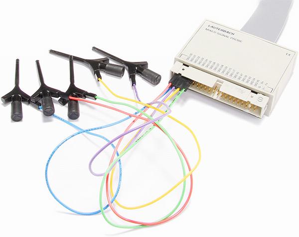 |
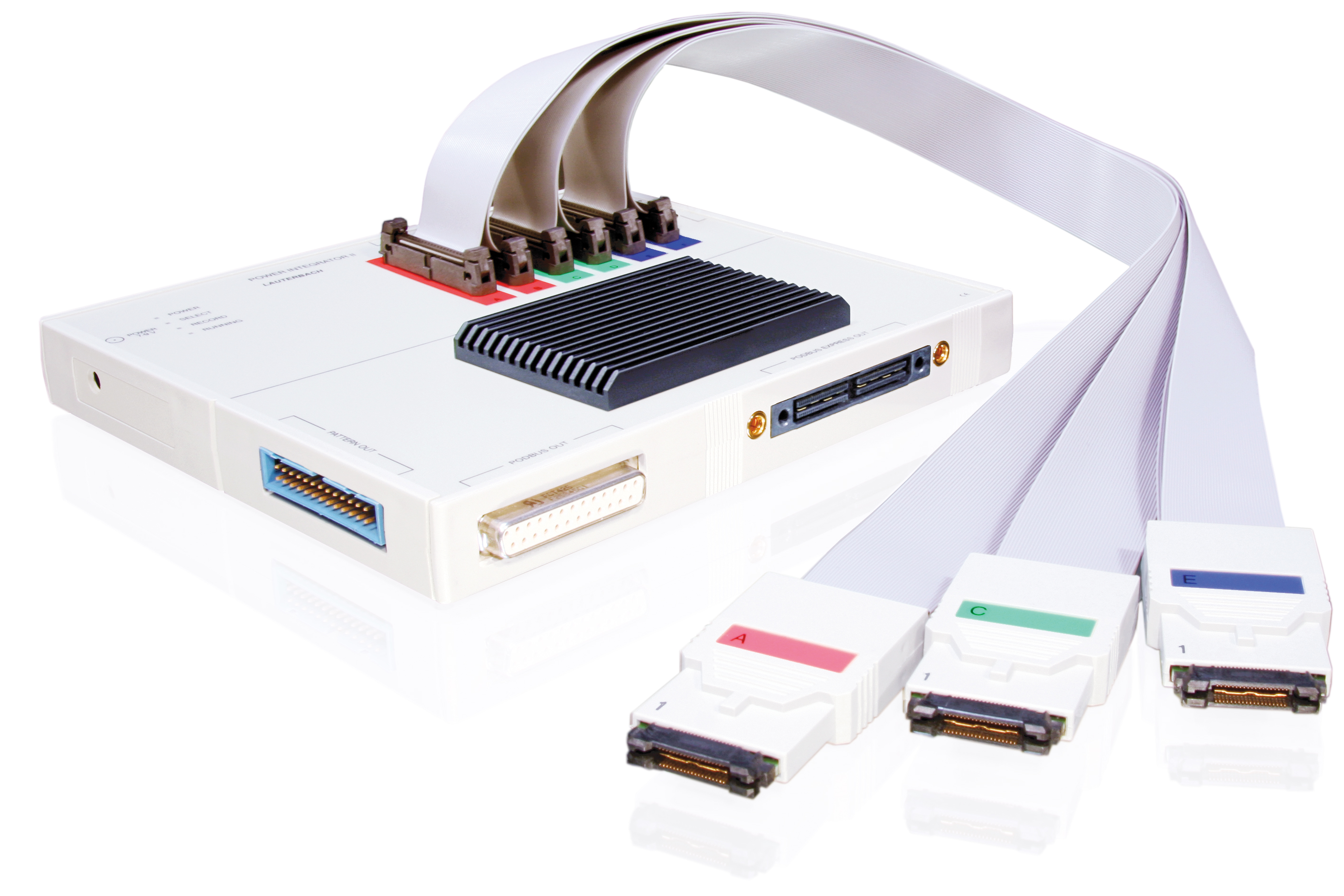 |
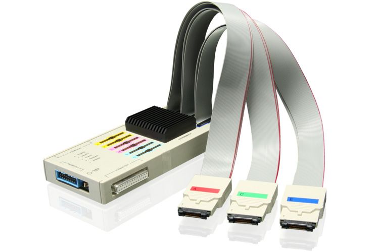 |
|
| Product | Mixed-Signal Probe | PowerIntegrator II | PowerIntegrator |
| Description | Allrounder (Most Popular) | Solution for extra long recordings of many signals | Solution for many signals or wide buses |
| Signal Type | Digital and Analog | Digital and Analog through specific probes | Digital and Analog through specific probes |
| Inputs | 12 digital channels, 6 single-ended voltage channels, 2 current measurements | Up to 102 digital channels, up to 8 signal ended voltage, up to 6 current measurements | Up to 204 digital channels, up to 8 signal ended voltage, up to 6 current measurements |
| Digital Input Voltage | 0-5V | 0-5V | 0-5V |
| Digital Threshold Voltage | 0.1V - 2.5V | 0.1V - 2.5V | 0.1V - 2.5V |
| Digital Sampling Rate | 200 MSamples/s per channel | 500 MSamples/s per channel | 500 MSamples/s per channel |
| Analog Input Voltage | -12V - +12V | 0V - +5V | 0V - +5V |
| Analog Resolution | 13 bit | 12 bit | 12 bit |
| Analog Sampling Rate | 1 MSample/s | 625 KSample/s | 625 KSample/s |
| Trigger Output | Not Available | 5 trigger outputs | Not Available |
| Compatible Modules | PowerTrace Serial 2, PowerTrace III, MicroTrace and CombiProbe 2 | PowerDebug II, PowerDebug PRO, PowerDebug X50/X51 | PowerDebug II, PowerDebug PRO, PowerDebug X50/X51, PowerDebug E40, PowerDebug USB 3.0 |
| Streaming Mode | Yes | Yes | No |
Questions?
Please contact us to get more information about any of ourTRACE32 products. If you want to place a quotation request, please contact our sales teams in your location.
