| Pin |
Direction |
Description |
| TCK|TCKC |
to CPU |
JTAG Clock. It is recommended to put a pull-down to GND on this signal. |
| TMS |
to CPU |
Standard JTAG TMS: It is recommended to put a pull-up to VTREF on this signal for standard 4-pin JTAG. |
| TMSC |
to/from CPU |
Compact JTAG TMSC: Your chip should have a bus-hold on this line for compact JTAG. |
| TDI |
to CPU |
JTAG TDI. It is recommended to put a pull-up to VTREF on this signal.
Only required for standard 4-pin JTAG / Optional signal for compact JTAG. |
| TDO |
from CPU |
JTAG TDO. (No pull-up or pull-down is required.)
Only required for standard 4-pin JTAG / Optional signal for compact JTAG. |
| TRST- |
to CPU |
JTAG Testport Reset.(Optional) This is an active low signal. A pull-up on the target is recommended. |
| RTCK |
from CPU |
JTAG Return Clock. (Optional, No pull-up or pull-down is required.) |
| VTREF |
from CPU |
Reference voltage. This voltage should indicate the nominal HIGH level the for the debug signals (JTAG, cJTAG, SWD).
So for example, if your signals have a voltage swing from 0 V ... 3.3 V, the VTREF pin should be connected to 3.3 V.
|
| SRST- |
to/from CPU |
System Reset Signal. (Optional)
If your target board has a low active CPU reset signal, you can
connect this low active reset signal to this pin.
This enables the debugger to detect a CPU reset.
Furthermore the debugger can drive this pin to GND to hold the CPU in
the reset state. The debugger drives this pin as open-drain,
so a pull-up is mandatory.
|
| EVTI |
to CPU |
Nexus Event In. (optional), only used with DesignWare ARC Trace to force a Nexus Synchronization Message. |
| EVTO |
from CPU |
Nexus Event Out. (optional) This pin is not used by ARC processors. (Leave open (N/C) if not used) |


 Debugger Adaptation for ARC


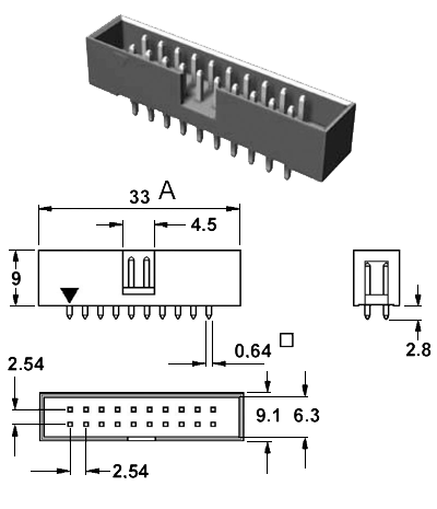
 Pinout