Adaptation for Nios II |
 |
|||||

|
||||||
| ||||||
 Debugger Adaptation for NIOS II
 |
 |
|
|
|
|
|
 Technical Support |
 |
| ||||||||||||||||||||||||||||||||||||||||||||||||||||||||||||||||||||||||||||||||||||||||||||||||||||||||||||||||||||||||||||||||||||||||||||||||||||||||||||||||||||||||||||||||||||||||||||||||||||||||||||||||||||||||||||||||||||||||
| Signal | Pin | Pin | Signal | ||
|---|---|---|---|---|---|
 | |||||
| TCK | 1 |  |  | 2 | GND |
| TDO | 3 | | | 4 | VTREF |
| TMS | 5 | | | 6 | N/C |
| N/C | 7 | | | 8 | RST- |
| TDI | 9 | | | 10 | GND |
 | |||||
| TCK | Jtag Clock. It is recommended to put a pull-DOWN to GND on this signal. |
| TMS | Jtag TMS. It is recommended to put a pull-UP to VCC on this signal. |
| TDI | Jtag TDI. It is recommended to put a pull-UP to VCC on this signal. |
| TDO | Jtag TDO. (No pull-up, or pull down is needed for this signal.) |
| VTREF | Reference voltage. This voltage should indicate the nominal HIGH level for the JTAG pins. So for example, if your JTAG signals have a voltage swing from 0V - 3.3V, the VTREF pin should be connected to 3.3V. |
| RST- | Optional. This pin is not used at the moment and is
intended for future use: If your board has a low active CPU reset signal, you can connect this low active reset signal to this pin. The debugger can drive this pin to GND to hold the CPU in the reset state. The debugger drives this pin as open-drain, so a pull-up is mandatory. |
 Dimension
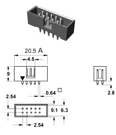
Connector Type
- This is a standard 10 pin double row (two rows of 5 pins) connector (pin to pin spacing: 2.54mm/0.100").
- If terminal strip without shroud is used, the spacing marked with "A" must be a minimum of 20.5mm/0.8".
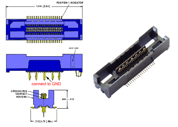
Connector MICTOR
| Signal | Pin | Pin | Signal | ||
|---|---|---|---|---|---|
 | |||||
| N/C | 1 |  |  | 2 | N/C |
| N/C | 3 | | | 4 | N/C |
| N/C | 5 | | | 6 | CLK |
| N/C | 7 | | | 8 | TRIGB |
| RST- | 9 | | | 10 | TRIGA |
| TDO | 11 | | | 12 | VTREF |
| N/C | 13 | | | 14 | N/C |
| TCK | 15 | | | 16 | D11 |
| TMS | 17 | | | 18 | D10 |
| TDI | 19 | | | 20 | D09 |
| N/C | 21 | | | 22 | D08 |
| N/C | 23 | | | 24 | D07 |
| N/C | 25 | | | 26 | D06 |
| D17 | 27 | | | 28 | D05 |
| D16 | 29 | | | 30 | D04 |
| D15 | 31 | | | 32 | D03 |
| D14 | 33 | | | 34 | D02 |
| D13 | 35 | | | 36 | D01 |
| D12 | 37 | | | 38 | D00 |
 | |||||
| Connect Pin 39,40,41,42 and 43 to GND | |||||
Signals for JTAG:
Only connect the JTAG signals on the MICTOR, iff you do not additionally have a 10 pin JTAG connector.
If you have both (a 10 pin connector for JTAG and a MICTOR), then only connect the trace signals to the MICTOR and leave the JTAG signals unconnected on the MICTOR. In this case the VTREF signal on the MICTOR indicates only the voltage level for the trace signals. The voltage level for the JTAG signals is then indicated by the VTREF signal on the 10 pin JTAG connector.
| TCK | Jtag Clock. It is recommended to put a pull-DOWN to GND on this signal. |
| TMS | Jtag TMS. It is recommended to put a pull-UP to VCC on this signal. |
| TDI | Jtag TDI. It is recommended to put a pull-UP to VCC on this signal. |
| TDO | Jtag TDO. (No pull-up, or pull down is needed for this signal.) |
| RST- | Optional. This pin is not used at the moment and is
intended for future use: If your board has a low active CPU reset signal, you can connect this low active reset signal to this pin. The debugger can drive this pin to GND to hold the CPU in the reset state. The debugger drives this pin as open-drain, so a pull-up is mandatory. |
| VTREF | Reference voltage. This voltage should indicate the nominal HIGH level for the trace pins and JTAG pins (if JTAG pins are in use). So for example, if your signals have a voltage swing from 0-3.3V, the VTREF pin should be connected to 3.3V. |
| CLK | Trace Clock. |
| D00 - D17 | Trace Data. |
| If possible the PCB trace lengths of CLK and D00-D17 should have the same lengths, since this signals carry high frequency data. | |
| TRIGA | Optional. Trace Trigger. At the moment the trace logic of the Nios II core supports one trigger output. This output can be used to trigger actions of the external trace (for example stopping a trace recording). |
| TRIGB | Optional. Trace Trigger. At the moment the trace logic of the Nios II core only supports one trigger output, so this pin is intended for future use. You might leave it unconnected, if you have not enough pins available on your FPGA. |
Dimension
Order No
TE Connectivity (TE) part numbers for suitable receptacles (for target)
2-5767004-2 RoHS compliant
 TE Connectivity (TE)
2-5767004-2 RoHS compliant
TE Connectivity (TE)
|
Copyright © 2024 Lauterbach GmbH, Altlaufstr.40, 85635 Höhenkirchen-Siegertsbrunn, Germany
Impressum
Privacy Policy
The information presented is intended to give overview information only. Changes and technical enhancements or modifications can be made without notice. Report Errors Last generated/modified: 07-Mar-2024 |
