Adaptation for MPC5XXX/SPC5XXX OnCE Debug Connector
 Products Products
| Order No. | Probe |
|---|
| LA-3725 | Conv. Mictor38 (NEXUS) to JTAG14 for MPC5xxx |
| LA-3873 | Conv. AUTO26 to JTAG14 OnCE |
| LA-7640 | Universal JTAG adapter for PowerPC architect. on request, please contact Lauterbach |
| LA-7753 | JTAG Debugger Qorivva MPC5xxx/SPC5xxx (ICD) out of production |
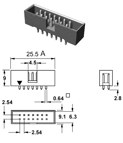
Connector 14 pin
|
Signal
| Pin
| | Pin
| Signal
|
|---|
| | |  | | |
| TDI | 1 |  |  | 2 | GND |
| TDO | 3 | | | 4 | GND |
| TCK | 5 | | | 6 | GND |
| (EVTI-) | 7 | | | 8 | N/C |
| RESET- | 9 | | | 10 | TMS |
| JTAG-VTREF | 11 | | | 12 | GND |
| (RDY-) | 13 | | | 14 | JCOMP |
| | |  | | |
Dimension
Connector Type
- This is a standard 14 pin double row (two rows of seven pins) connector (pin to pin spacing: 2.54mm/0.100").
- If terminal strip without shroud is used, the spacing marked with "A" must be a minimum of 23mm/0.9".
JTAG connector recommendations
- TDI, TDO, TCK, TMS and JCOMP- should be connected directly to the CPU. Don't connect serial resistors or RC terminations to those signals.
- Avoid routing the JTAG signals close to the NEXUS signals.
- JTAG-VTREF (pin 11) must match the JTAG I/O voltage of the processor. JTAG-VREF should have a resistance less than 5kOhm for 3.0~5.0V, less than 2kOhm for 1.8~3.0V.
- The RDY- signal (pin 13) is optional.
If the signal is not available, or can not be connected because of other reasons, the RDY- pin on the debug connector should be connected to GND.
If the RDY- signal on the debug connector is not connected, set SYStem.Option.NOJTAGRDY ON.
- EVTI (pin 7) is optional. On this debug cable EVTI is N/C. It is however recommended to connect EVTI for future use (e.g. for automotive debug cable + adapter LA-3873).
- If the signal JCOMP (pin 14) is not available on the used processor/package type, leave the JCOMP pin on the debug connector unconnected. If JCOMP is available on the processor package, it must be connected to the debug connector.
- We recommend to follow
Freescale's Application Note AN2614.
Debug Cable Information
- When the debugger is inactive (SYStem.Mode.DOWN and NoDebug), all output pins of the debug cable are tri-stated (hot-plug capability)
- During the debug session: TDI, TCK, TMS and JCOMP- are driven to both low and high levels. Only RESET is an open-drain output. The voltage level of a pin driven to high is the same soltage level as connected to VDD target (pin 11).
- All output signals of the debug cable have a 47 Ohm serial termination. Usually no further termination is needed on the target hardware.
- Maximum supported voltage range (check debug cable's serial number CYYMMxxxxxx):
- Debug cable produced before 09/2009: 1.8-5.5V
- Debug cable produced 09/2009 or later: 0.9-5.5V
- Input impedance on VDD target (pin 11):
- Debug cable produced before 09/2009: >45 kOhm
- Debug cable produced 09/2009 or later: >90 kOhm
- IEEE 1149.7 (aka cJTAG) supported by debug cables produced 09/2009 or later.
 Available Adapters Available Adapters
| Order-Nr. | Connector to target | Connector(s) to debug cable | Connector to trace module |
| LA-3723 | Mictor38 (NEXUS-MPC5XXX) | JTAG14 (MPC5XXX) | - |
| LA-3843 | ECU14 | JTAG14 (MPC5XXX) + JTAG16 (TriCore) + AUTO26 | - |
| LA-3871 | Samtec34 Power.Org pinout | JTAG14 (MPC5XXX) + AUTO26 | Samtec40 (Aurora preprocessor) |
| LA-3872 | Samtec22 Power.Org pinout | JTAG14 (MPC5XXX) + AUTO26 | Samtec40 (Aurora preprocessor) |
| LA-3876 | AUTO26/20/10 | JTAG14 (MPC5XXX) | - |
|


 Adaptation for MPC5XXX/SPC5XXX OnCE Debug Connector